In the previous article of this series we built a Raspberry Pi distributed cluster from four Raspberry Pi 4Bs. In this article we are going to begin preparing the cluster to work with the SLURM job scheduler. We will install the latest version of Ubuntu Server Linux on each of the RPis. Then we will configure both the network and the shared storage used by the RPis in order to allow SLURM to communicate with each node. In the next article of the series we will install SLURM itself.
This article closely follows the approach discussed in the excellent three part series written by Garrett Mills. We will also be making changes where necessary, particularly around optimising for usage of QSTrader. We highly recommend taking a read of his articles for additional details.
Linux Command Line
The content of this article assumes a basic familiarity with the Linux command line. We will be using standard Linux commands such as ssh, mkfs, ifconfig, nmap, chown and chmod. If you want a refresher on using the Linux command line prior to following this article we highly recommend The Linux Command Line, 2nd Ed. by William Shotts, which covers these commands in detail from an introductory standpoint.
We will begin by downloading the Ubuntu Server ISO disk image and 'flashing' it to each of the MicroSD cards that were described in the previous article. We will then configure the IP addresses and hostnames of the RPis. Then we will set up the shared storage using the 128GB USB key that was discussed in the previous post. At this point we will be ready to install and configure SLURM, which will be the topic of the subsequent article.
Flash SD Cards with Ubuntu 22.04
At the time of writing the latest version of Ubuntu Server with long term support (LTS) is Ubuntu 22.04. While it is certainly possible to use Raspberry Pi OS, with minimal change in the instructions beyond some configuration, we have opted for Ubuntu in this article series.
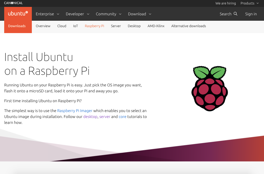
The first task is to download the Ubuntu Server ISO image for Raspberry Pi that we will be placing on our MicroSD cards. Head over to the Ubuntu Server Raspberry Pi site in your web browser here. You will see the following screen:
Scroll down and you will see a heading titled 'Download Ubuntu Server':
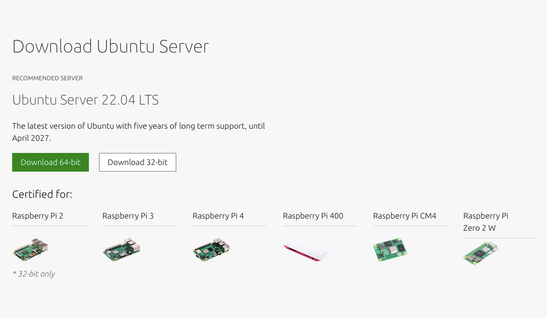
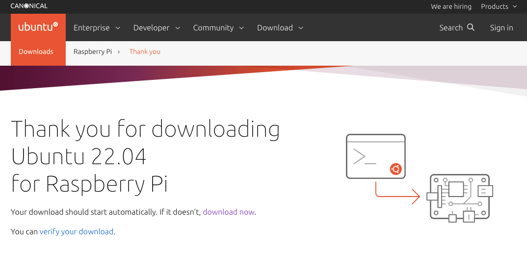
Click the button titled 'Download 64-bit' and you will see the following 'thank you' screen:
The download modal will pop up and ask whether we want to open or save the file. Click to save the file for later use. The Ubuntu Server ISO is a reasonably big file so it may take some time to download the image.
While Ubuntu is downloading we also need to obtain some free software to 'flash' Ubuntu on the MicroSD cards. This will allow the RPis to use them as boot drives. As suggested by Garett Mills in his original article series we are going to use an open source tool called balenaEtcher. Head on over to the site here in your web browser and you will see the following page:

Click the Download button and follow the installation instructions to install the tool. At this stage you will also need to insert the MicroSD into your computer's MicroSD port.
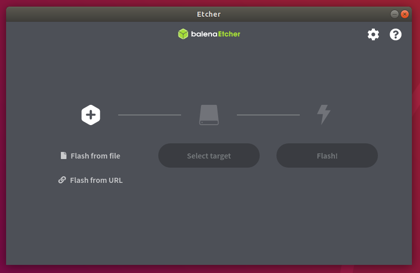
Once Balena Etcher is installed load it up and you will be see the following screen (see Figure 5):
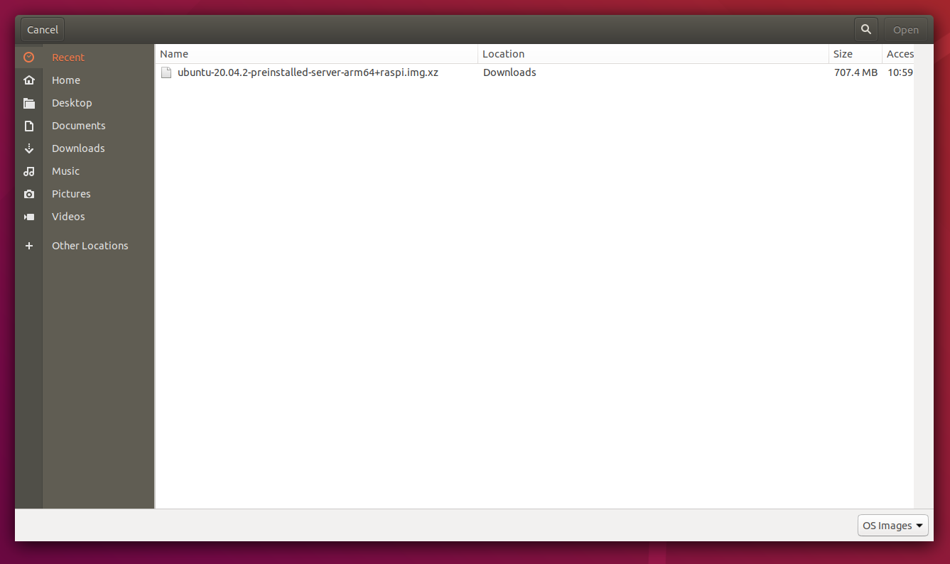
Click on the large plus symbol above 'Flash from file'. You will be presented with a file selection dialog (see Figure 6). Navigate to the location where the Ubuntu Server ISO was downloaded to (typically `Downloads/` in your operating system's home directory) and select the ISO file:
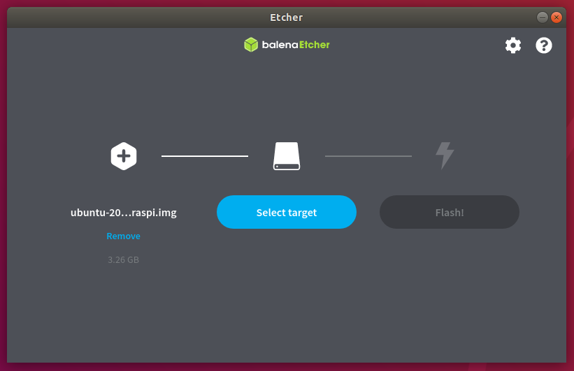
The Balena Etcher screen will show that the Ubuntu Server ISO has been selected. The next step is to select the target to flash the ISO to. Click on the 'Select Target' button (see Figure 7):
You will then see a screen showing 'Generic MassStorageClass' with size of 32Gb. This is the MicroSD card. Click on the checkbox next to the 'Generic MassStorageClass' and then the Select (1) button (see Figure 8):

Now that the MicroSD card has been selected Balena Etcher will show both the ISO selected and the location to flash to (see Figure 9). Click on the 'Flash!' button and wait for the process to complete (it can take a few minutes):

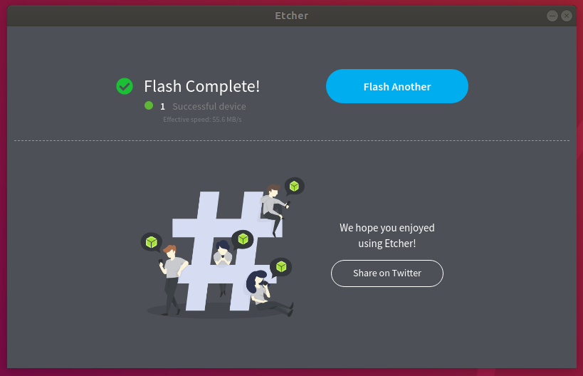
Once complete Balena Etcher will ask whether you wish to flash another disk (see Figure 10):
Repeat the process for all four cards and then insert the SD cards into the appropriate ports on each Raspberry Pi.
Network Configuration
It is now time to configure the RPis to communicate with each other. The configuration approach will depend somewhat on your personal network setup and how much control you have over allocating IP addresses to the RPis. Typically this will involve using an ISP-supplied router/modem to access the internet, which is able to provide IP addresses to all connected devices automatically. This makes use of a protocol known as Dynamic Host Configuration Protocol (DHCP). DHCP dynamically allocates IP addresses to devices plugged in to the router, either via ethernet or WiFi.
However we wish to assign static IP addresses, which are addresses that will persist across RPi reboots. This allows SLURM to know where all of the individual RPi nodes are on the network. In this article we are going to assume the usage of ethernet connectivity and the ability to assign static IP addresses within your router. Unfortunately it is beyond the scope of this article to describe how to assign static IP addresses within a router interface, due to the extensive variations between manufacturers and ISPs. It will be necessary to consult your router's manual, or carry out an internet search on how to carry this out.
The first step is to plug the 8-port network switch discussed in the previous article into your router via ethernet and power it on. Activity lights will blink periodically to show that the switch is receiving network traffic from the router. The next step is to connect a single Raspberry Pi into this network switch with one of the previously ordered ethernet cables. The ethernet port on the RPi is located adjacent to the USB ports. Then plug in the USB-C power cable from the power bar, purchased in the previous article to the RPi. The Raspberry Pi will now boot up.
Since we have not attached a monitor, mouse or keyboard it will be necessary to configure the RPi using a headless remote approach via Secure SHell (ssh). UNIX-based systems such as macOS or Linux will likely have an ssh client built in, which can be accessed from the terminal. On Windows it is common to use Putty, which can be downloaded here.
However, in order to be able to connect to the booted RPi via ssh it is necessary to know its DHCP-assigned IP address on the network. To find this out it is possible to use a tool called nmap. The remainder of the article assumes usage of a macOS or Linux-based system for carrying these commands out. Similar commands exist for the Windows shell.
Open up a terminal shell and type the following command:
ifconfig
You may be presented with a message saying that ifconfig is not installed. To remedy this (on Ubuntu/Debian based systems) type the following and accept the installation options:
sudo apt-get install net-tools
Re-run ifconfig and you will see output similar to the following:
lo0: flags=8049 mtu 16384
    options=1203
    inet 127.0.0.1 netmask 0xff000000
    inet6 ::1 prefixlen 128
    inet6 fe80::1%lo0 prefixlen 64 scopeid 0x1
    nd6 options=201
gif0: flags=8010 mtu 1280
stf0: flags=0<> mtu 1280
XHC20: flags=0<> mtu 0
en1: flags=8963 mtu 1500
    options=60
    ether 5b:00:22:ae:1c:32
    media: autoselect
    status: inactive
en0: flags=8863 mtu 1500
    ether b4:21:aa:35:b8:ca
    inet6 ad91::2ac2:2752:e483:17a8%en0 prefixlen 64 secured scopeid 0x7
    inet 192.168.0.103 netmask 0xffffff00 broadcast 192.168.0.255
    nd6 options=201
    media: autoselect
    status: active
We are looking for the IP address of the current system. It will likely be of the form 192.168.x.y, 172.x.y.z or 10.x.y.z. We are interested in the first three parts of this address as typical DHCP configurations on most home routers will assign an IP in the range x.y.z.2 to x.y.z.254. In the code snippet above this corresponds to the inet 192.168.0.103 ... line.
Once you have identified this address we can utilise nmap to scan for other hosts on this same subnet (that is, all hosts which share the same first three parts of the address), which should help us identify the IP address of the RPi.
Run the following command:
nmap -sP 192.168.1.0/24
Where it will be necessary to replace 192.168.1 with the appropriate subnet obtained from ifconfig.
The output will look similar to the following:
Starting Nmap 7.80 ( https://nmap.org ) at 2021-01-01 10:24 GMT
Nmap scan report for 192.168.1.1
Host is up (0.0056s latency).
Nmap scan report for 192.168.1.104
Host is up (0.0044s latency).
Nmap scan report for 192.168.1.105
Host is up (0.013s latency).
Nmap done: 256 IP addresses (3 hosts up) scanned in 2.72 seconds
One of these IP addresses will belong to the RPi. An alternative approach to identify it is to log in to your router's web interface and look for a page titled similar to 'ARP table' or 'DHCP Client List', which should list all of the hosts connected to the RPi and their current IP address.
Once the IP address of the RPI has been correctly identified it is possible to remotely connect to the RPi via ssh. Type the following command on your macOs or Linux terminal, or utilise Putty on Windows:
ssh ubuntu@YOUR-IP-ADDRESS
Where YOUR-IP-ADDRESS needs to be replaced with the previously identified RPi IP address found via nmap.
You will be asked to enter a password. The default password is either ubuntu or raspberry. You should now be logged in to your RPi via ssh.
Raspberry Pi Setup
The first task to carry out involves updating Ubuntu's list of system packages and then upgrading them. To carry this out run the following commands:
sudo apt-get update
And then:
sudo apt-get upgrade
You may receive a message similar to the following when you run the second command:
E: Could not get lock /var/lib/dpkg/lock - open (11 Resource temporarily unavailable)
E: Unable to lock the administration directory (/var/lib/dpkg/) is another process using it?
This is essentially telling us that the Ubuntu package manager is currently unable to upgrade the packages because the RPi itself has already begun an automated upgrade procedure and has the locked the package state files. Unfortunately this can take some time to finish (approximately 15-30 minutes) so if this occurs it will be necessary to wait and try running the upgrade command again once it is complete.
The next task is to install various useful system packages and tools. In particular we are going to install build-essential, which contains the GNU Compiler Collection for compiling software from source; htop, which allows us to see what commands are currently running on the system; net-tools, which allow us to use ifconfig on the RPis; screen, which allows us to persist our terminal session between log-outs and vim, which is a terminal text editing tool. The latter can be replaced with one's favourite terminal editor such as nano or emacs:
sudo apt-get install build-essential htop net-tools screen vim
The next step is to provide a hostname for the RPi. Due to how SLURM works it is necessary to utilise a naming convention with an incrementing index at the end. Hence, if you wish to name your system rpicluster, the hostnames will need to be rpicluster01 through to rpicluster04 (assuming you are using four RPis for this cluster).
Feel free to pick an appropriate hostname (by replacing rpicluster with your chosen name), but do ensure that it has 01 at the end. Let's now set the hostname. Type the following into the SSH terminal
sudo hostname rpicluster01
In addition we need to open the /etc/hostname file and ensure the hostname is set here. Run the following command:
sudo vim /etc/hostname
In Vim, to type it will be necessary to press i, then type rpicluster01 (or your preferred hostname), unless it is already there. To save and quit, press Escape, type :wq.
We will also need to modify the /etc/hosts file that tells the RPi about itself and other hostnames on the network. Type the following command:
sudo vim /etc/hosts
You will see a set of IP addresses and hostnames. It is likely that you will only have the following:
127.0.0.1  localhost

# The following lines are desirable for IPv6 capable hosts
..
..
Where the .. represent a list of IPv6 addresses.
It is necessary to add the current IP address beneath the 127.0.0.1 localhost line along with the hostname. Once again, type i to type and write a new line such that the file looks like the following:
127.0.0.1  localhost
192.168.1.101  rpicluster01

# The following lines are desirable for IPv6 capable hosts
..
..
Making sure to replace both 192.168.1.101 with your own IP address found from nmap earlier on and rpicluster with your desired hostname.
The next step is to install the ntpdate utility, which will periodically synchronise the date and time on the RPi with a Network Time Protocol (NTP) server. This is to ensure that SLURM has accurate timings between the RPis. Type the following command to install it:
sudo apt install ntpdate -y
Now that we have carried out this initial configuration we can reboot the RPi:
sudo reboot
This will disconnect the SSH session to your local machine. After a short while it will be possible to reconnect via the original command above, run on your local machine's terminal (or Putty):
ssh ubuntu@YOUR-IP-ADDRESS
Ensuring once again to replace YOUR-IP-ADDRESS with that found by nmap.
This process now needs to be repeated for each of the RPi secondary nodes in turn, ensuring to name them sequentially with HOSTNAME02, HOSTNAME03 and HOSTNAME04, where HOSTNAME can be replaced with the same hostname used for the primary RPi node.
Configuring Shared Storage
The next task is to configure the RPis to utilise the previously purchased 128Gb USB key as a shared network drive. This allows any programs executed by SLURM to persist data that can be seen by all of the RPi nodes.
The first step is to plug the USB key into the primary RPi node, which is the one we have been configuring so far.
Once it has been plugged in we need to run a tool called lsblk, which lists the block devices such as hard disks and USB devices attached to the system. Run the following command on the primary RPi node:
lsblk
You will see output that looks similar to the following:
NAME        MAJ:MIN RM   SIZE RO TYPE MOUNTPOINT
loop0         7:0    0  48.9M  1 loop /snap/core18/1949
loop1         7:1    0    27M  1 loop /snap/snapd/10709
loop2         7:2    0  61.6M  1 loop /snap/lxd/19040
loop3         7:3    0  28.2M  1 loop /snap/snapd/13643
loop4         7:4    0    49M  1 loop /snap/core18/2248
loop5         7:5    0  57.4M  1 loop /snap/core20/1171
loop6         7:6    0  60.4M  1 loop /snap/lxd/21544
sda           8:0    1 114.6G  0 disk
|-sda1        8:1    1   212K  0 part
|-sda2        8:2    1   2.8M  0 part
|-sda3        8:3    1  1001M  0 part
|-sda4        8:4    1   300K  0 part
mmcblk0     179:0    0  29.8G  0 disk
|-mmcblk0p1 179:1    0   256M  0 part /boot/firmware
|-mmcblk0p2 179:2    0  29.6G  0 part /
In the output above you can see an entry called sda and another called mmcblk0. Notice that sda has a size of approximately 114Gb, while mmcblk0 has a size of roughly 30Gb. Thus sda is the 128Gb flash drive and mmcblk0 is the 32Gb Micro SD card.
We now wish to format the USB key to utilise the ext4 journaling filesystem. To achieve this we can use a tool called mkfs.ext4, which makes the ext4 filesystem on the disk. Run the following command on the primary RPi node (the one with the USB key plugged in):
sudo mkfs.ext4 /dev/sda1
We are now going to create the shared directory, called sharedfs, across each of the four RPi nodes. Then we are going to change the ownership (using the chown command) and change the permissions (using the chmod command) for the directory. Run these three commands across all RPi nodes:
sudo mkdir /sharedfs
sudo chown nobody.nogroup -R /sharedfs
sudo chmod 777 -R /sharedfs
This gives permissive access to the sharedfs network drive across all RPis.
In order for this drive to persist across reboots it is necessary to modify the fstab file to mount the USB key on boot of the RPi. We can use a utility called blkid to achieve this. On the primary RPi node run the following command:
blkid
Now look for the UUID from the /dev/sda1 line. It will be similar to the following:
UUID="01c788f2-0cbd-4a18-b3e2-47cd6b00f87d"
Copy this UUID to the clipboard and edit the fstab file on the primary RPi node:
sudo vim /etc/fstab
Once again, press the i key to edit and then add the following line at the end of the file, making sure to replace the example UUID given here with the one you obtained previously with blkid:
UUID=01c788f2-0cbd-4a18-b3e2-47cd6b00f87d /sharedfs ext4 defaults 0 2
Now we can mount the drive with the following command:
sudo mount -a
Ensure that the following ownership and permissions are set. Since we are running this in a controlled home network environment these permissions can be very permissive. If you are considering running this in a less controlled environment (e.g. some form of shared network) then you will need to consider what sort of permissions you wish to use. That topic is beyond the scope of this article however.
Run the following commands to set the permissions and ownership:
sudo chown nobody.nogroup -R /sharedfs
sudo chmod -R 777 /sharedfs
Now that the drive is set to be automatically mounted on boot of the RPi we need to export it as a network file system so that the remaining RPi nodes can connect to it. Run the following command on the primary RPi node only:
sudo apt install nfs-kernel-server -y
We need to edit the /etc/exports file. Use Vim or your preferred editor to open the file:
sudo vim /etc/exports
Now add the following line to the file, ensuring to replace IPADDRESS with your local IP address subnet.
For instance, if your IP address was identified as 192.168.1.103, then you will need to enter 192.168.1.0/24 (note the 0/24 at the end) instead of IPADDRESS below:
/sharedfs IPADDRESS(rw,sync,no_root_squash,no_subtree_check)
Finally we need to update the network fileshare kernel server. Run the following command on the primary RPi node:
sudo exportfs -a
The next step is to configure the individual clients to use the network file store. On each of the secondary nodes (02-04) install the network file store common tools package:
sudo apt install nfs-common -y
Next, on each of the secondary nodes open up the /etc/fstab file:
sudo vim /etc/fstab
Add the following line ensuring to replace PRIMARYNODEIPADDRESS with the IP address of the primary node as identified above using nmap. This tells the secondary nodes where to actually look for the shared filesystem:
PRIMARYNODEIPADDRESS:/sharedfs /sharedfs nfs defaults 0 0
Run the following command across all secondary nodes to mount the shared network file system:
sudo mount -a
Change the ownership of the filesystem on each secondary node to give it loose permissions:
sudo chmod -R 777 /sharedfs
At this point it should be possible to create a file from one of the RPi nodes and have it show up in each of the other three nodes. To do this simply type the following on one of the nodes (primary or secondary):
touch /sharedfs/test_file.txt
Check that this file can be seen by running the ls directory listing command across all nodes:
ls /sharedfs
You should be able to see the file across all four nodes.
This now completes the setup of the shared network drive. In the next article (coming soon) we are going to install the SLURM scheduler on the Raspberry Pi nodes.